SunSprout Satellite
The SunSprout Satellite is the dedicated remote sensor endpoint for the SunSprout ecosystem. It terminates a long differential-I2C cable run from the SunSprout Hub, restores standard local I2C signaling, and monitors up to four capacitive soil-moisture probes plus a 1-Wire soil-temperature probe.
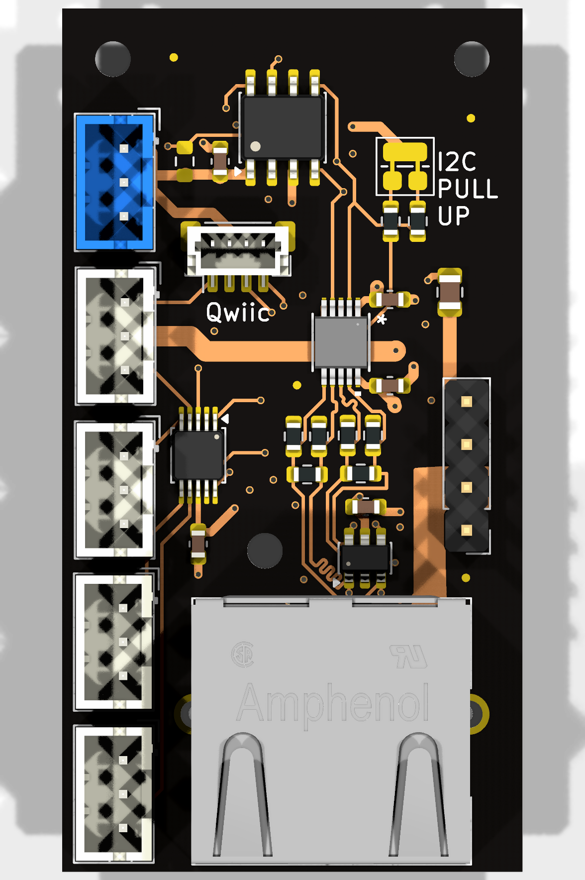
What is the Satellite?
The SunSprout Satellite functions as a remote garden/agricultural probe station. Where standard I2C buses degrade after a few tens of centimetres, the Satellite connects to the Hub over standard Category-rated twisted-pair patch cable using differential signaling. The PCA9615 datasheet quotes a 3 m cable at full speed, and longer runs at lower clock speeds; long runs have not been tested on this board.
At the endpoint, the board translates the differential clock and data signals back into standard 3.3V single-ended I2C, hosts an onboard 16-bit analog-to-digital converter (ADS1115) and a hardware 1-Wire master bridge (DS2482-100+), and distributes power and ground to local sensors.
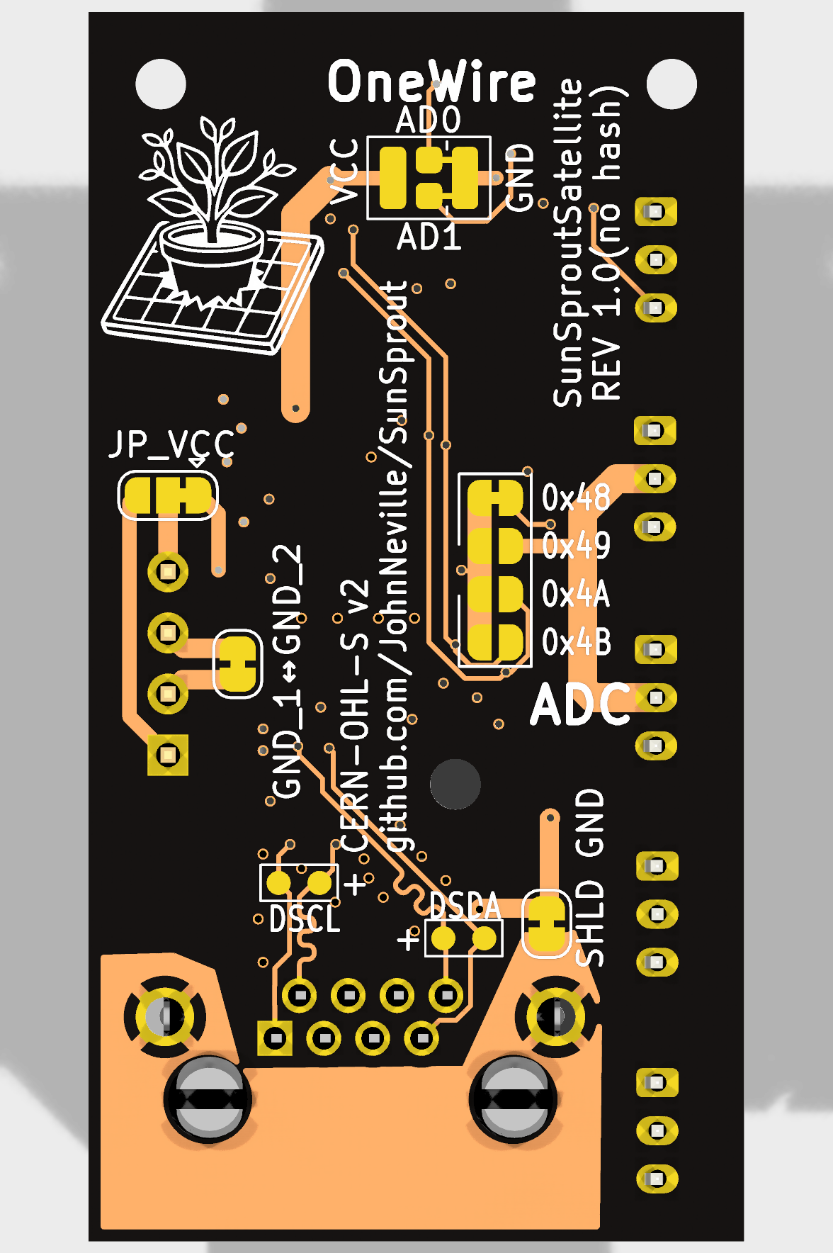
Physical Specifications
| Property | Value | Notes |
|---|---|---|
| Form factor | 27.25 × 51.10 mm | Slender rectangular profile fits small waterproof enclosures or conduit |
| Board thickness | 1.6 mm | Standard FR4 |
| Layer stackup | 4 copper layers | Signals on the outer layers; the two inner layers carry ground and power zones |
| Mounting | 3× M2 non-plated holes | 3.0 mm corner inset at top; 1 mid-board support hole |
| Primary interface | 1× Amphenol RJHSE5380 | 8P8C (RJ45) jack with metal EMI shield |
| Sensor ports | 5× JST PH 2.0mm 3-pin | 4 moisture probe inputs + 1 temperature probe input |
| Auxiliary ports | 2.54mm headers, plus a Qwiic port | J7 taps the cable's power and ground pairs, J9 is the local 3.3V and ground header, and J8 is a JST SH Qwiic / STEMMA QT port |
Capabilities & Architecture
1. Differential I2C Bus Endpoint (PCA9615)
- PCA9615DPZ differential buffer translates
DSCL+/DSCL-andDSDA+/DSDA-back into localSCL_LOCALandSDA_LOCAL. - Fixed Onboard Termination: Populated with matched resistor ladders (bias pull-ups to
RJ45_VCC_1, line-matching resistors, and bias pull-downs toRJ45_GND_1) across both differential pairs. This ensures proper transmission line termination without loose plug-in resistors. - TVS / ESD Protection: An onboard USBLC6-4SC6 transient voltage suppressor array clamps all four differential lines against outdoor static and handling discharge.
2. High-Precision Soil Moisture Monitoring (ADS1115)
- ADS1115IDGS 16-bit 4-channel delta-sigma ADC with programmable gain amplifier and internal reference.
- Reads analog voltage outputs from up to four independent capacitive soil-moisture probes (e.g., DFRobot SEN0193 / Gravity interface).
- Four 3-pin vertical JST PH connectors (
J2–J5) distributeGND,SAT_3V3, and signal lines (MOIST1–MOIST4). - Configurable I2C Address (
JP1): 4-way solder jumper on the bottom side selects addresses0x48,0x49,0x4A, or0x4B(0x48default bridged).
3. Dedicated 1-Wire Temperature Bridge (DS2482-100+)
- Hardware I2C-to-1-Wire master bridge eliminates software bit-banging and timing jitter over long probe leads.
- Dedicated 3-pin vertical JST PH connector (
J6) connects a waterproof DS18B20 digital temperature probe (SAT_3V3,GND,ONEWIRE_DQ). - The DS2482's internal pull-up drives the 1-Wire line. A footprint for an optional external 4.7kΩ pull-up (
R9) is left unpopulated. - Configurable I2C Address (
JP16): Dual solder jumper selects addresses0x18(factory default),0x19,0x1A, or0x1B.
4. Power & Auxiliary Flexibility
- Decoupled Power Architecture: PCA9615 transceiver power (
VDDB), the differential termination bias networks, and the ESD clamp array connect directly to the cable supply nets (RJ45_VCC_1/RJ45_GND_1). Those nets are joined to the local rails byJP18andJP17, which are bridged by default. - Bulk Cable Reservoir (
C1): An onboard 22 µF bulk capacitor (C1) sits directly acrossRJ45_VCC_1andRJ45_GND_1right at the cable entry, dampening inductive cable ringing and buffering transient load steps. Dedicated 100 nF ceramic decoupling capacitors sit directly adjacent to every active IC pin. - Factory Default Operation (Zero Overhead): Pre-bridged cuttable solder jumpers
JP18(RJ45_VCC_1$\leftrightarrow$SAT_3V3) andJP17(RJ45_GND_1$\leftrightarrow$GND) power the board directly from the Hub's regulated 3.3V rail over Pair 1 out of the box with zero external wiring. - Cable Power Breakout Header (
J7): Exposes raw Pair 1 (RJ45_VCC_1,RJ45_GND_1) and Pair 3 (RJ45_VCC_2,RJ45_GND_2) conductors on a 2.54mm pitch header for secondary power injection or tapping. - Satellite Local Power Header (
J9) & Long-Distance Regulation: A 2-pin 2.54mm header (SAT_3V3,GND). On long cable runs where cable IR drop is non-negligible, users can sliceJP18(and optionallyJP17), send higher voltage (12V/24V) down Pair 3 (cutJP2andJP3on the hub first), and connect an off-the-shelf compact buck regulator betweenJ7andJ9. - Single-Cut Pull-Up Jumper (
JP11): A custom 3-pad solder jumper with a single collinear cut channel allows disconnecting both local 4.7kΩ I2C pull-ups simultaneously with a single craft knife slice. - Power Status LED (
LED1) & Cuttable Jumper (JP19): A green 0805 power indicator illuminates wheneverSAT_3V3is energized. Solder jumperJP19allows severing the LED ground connection with a hobby knife to remove the LED's current draw in battery-powered applications. - Cable Shield Isolation (
JP13): Cuttable solder jumper on the bottom side connects the RJ45 metal shield toRJ45_GND_1by default, allowing single-point grounding configurations when required.
Further Reading
- Dimensions & Mounting — Exact outline, mounting hole locations, connector courtyard extents, and enclosure clearance guidance.
- Hub Overview — Main system controller, solar MPPT charger, and differential I2C driver.
- Design Files — Schematic PDFs, Gerbers, and 3D CAD STEP models.